Michael Douglas
Electrical engineer (B.S., University of Maryland). I design, build and test hardware end to end: brushless motors and motor controllers, a custom quadcopter with its own flight firmware, and the rigs to test them safely.
Custom brushless outrunner motor
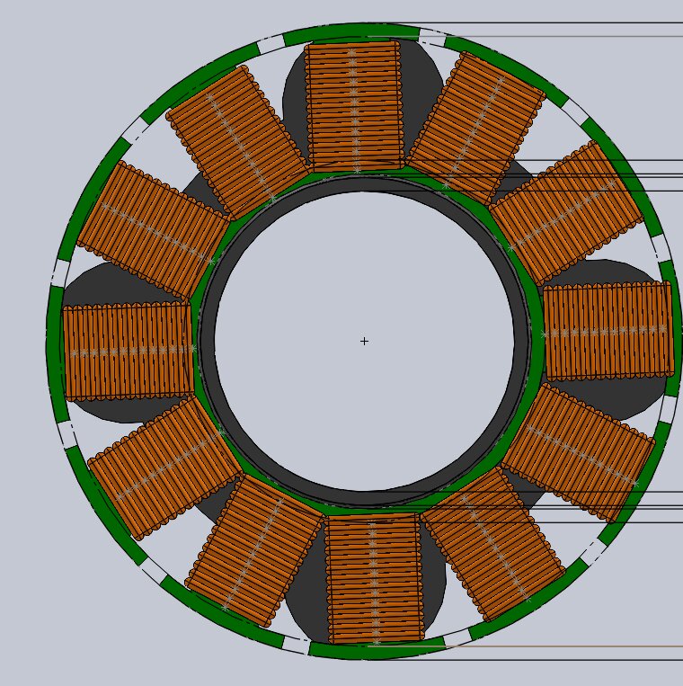
Understand, then eventually replace, the off-the-shelf motors on my quadcopter.
Built an air-core PLA prototype first to prove the winding and test method, then redesigned with an iron core, changing one variable so the gain is measurable. Lamination went through five DXF revisions (V1–V5).
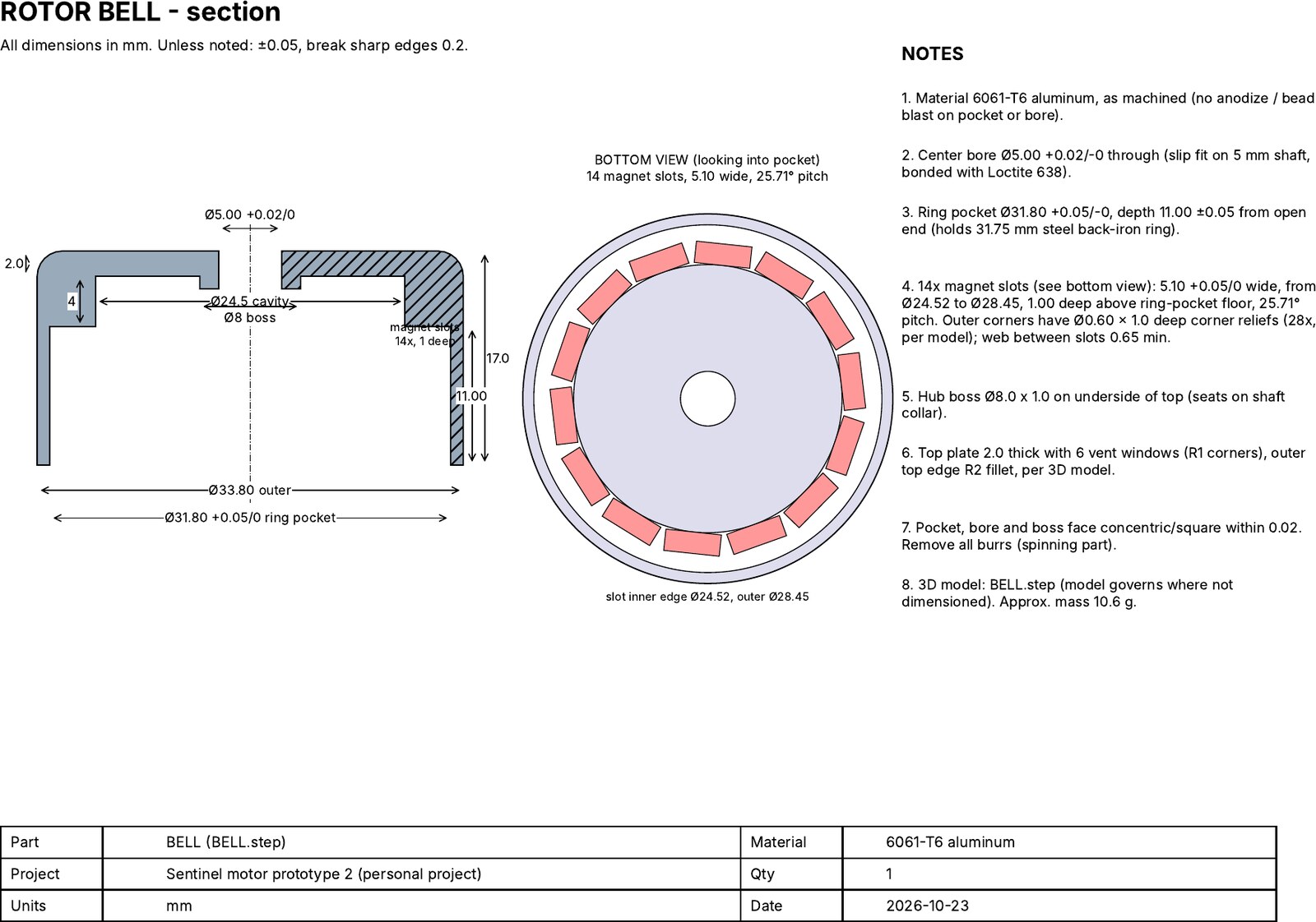
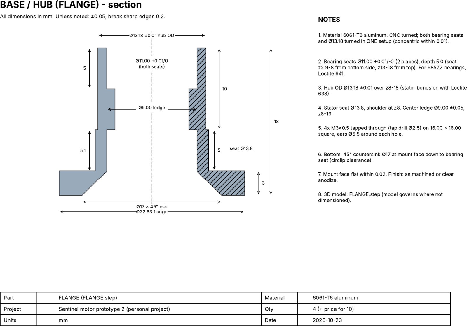
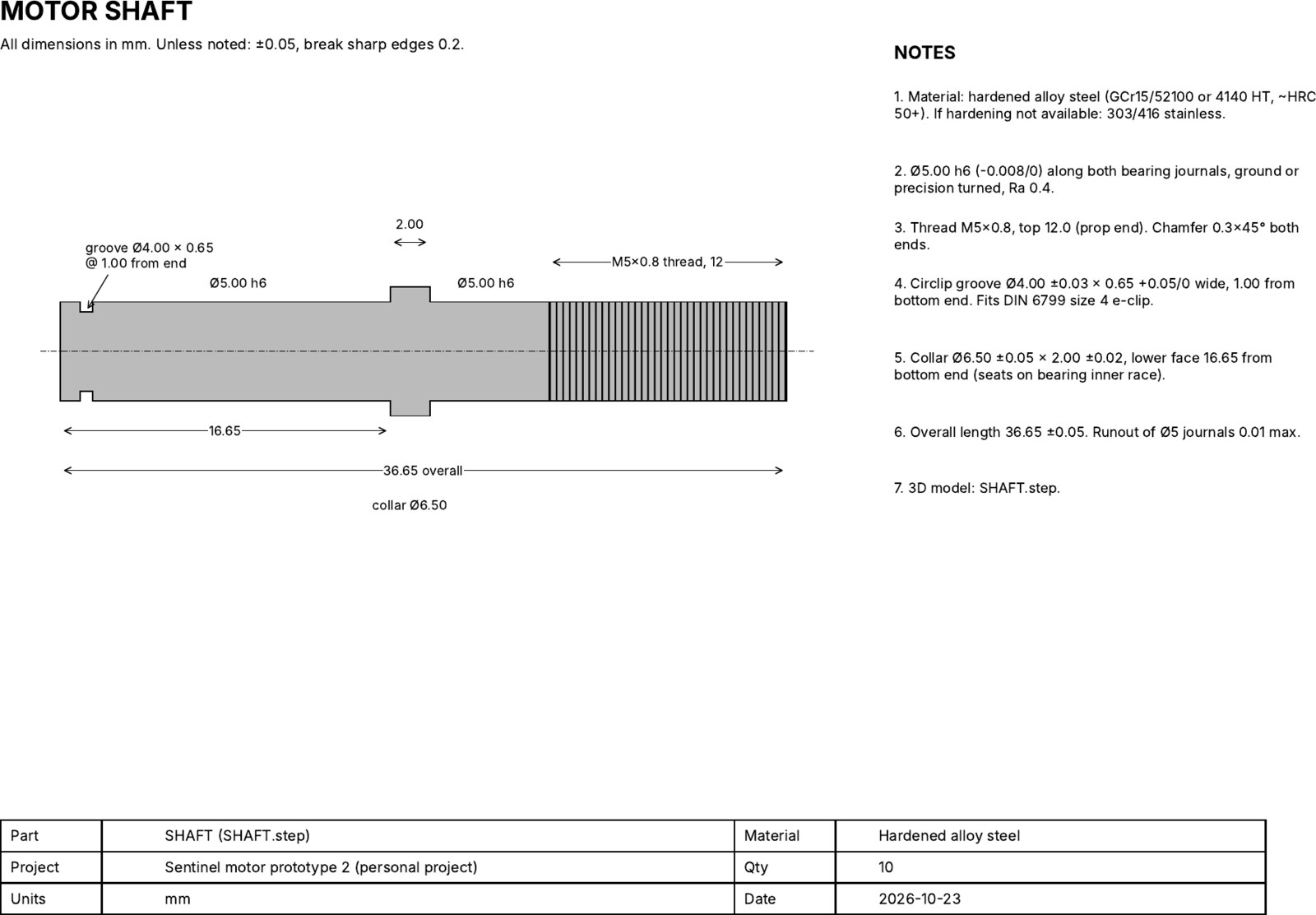
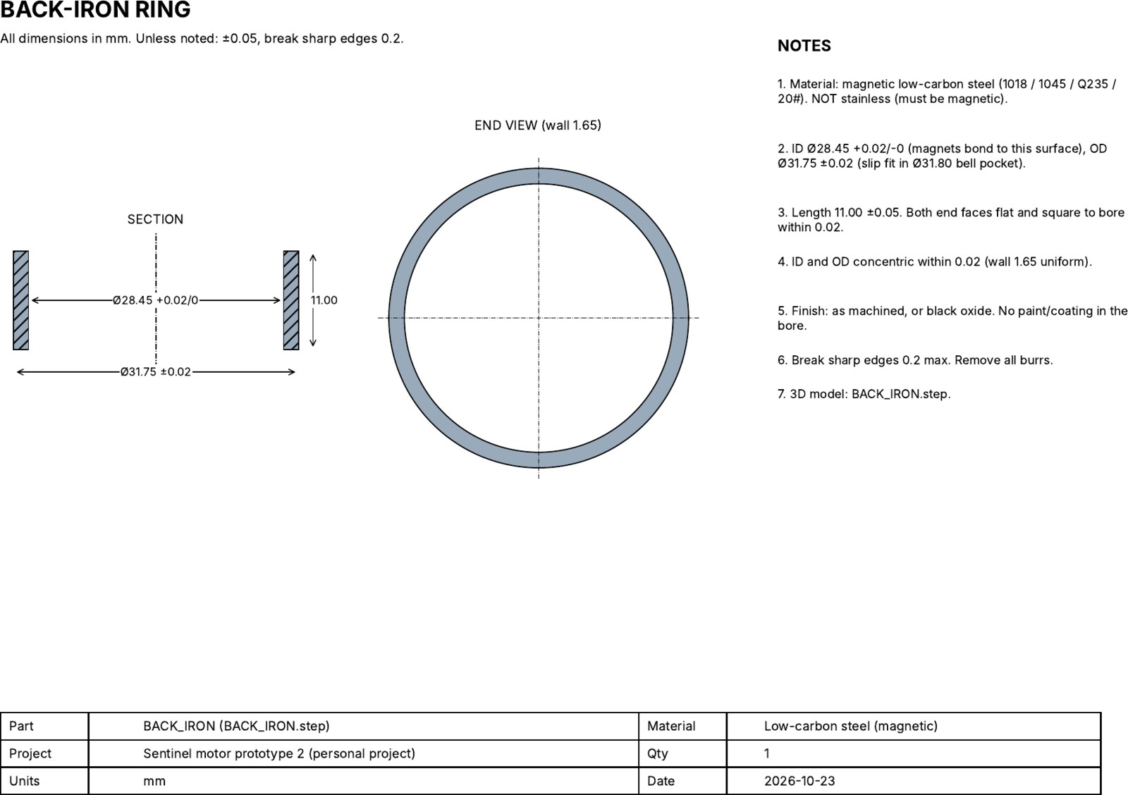
Prototype 1 spins on a commercial BLHeli ESC, with back-EMF captured on a scope. Prototype 2 design is frozen and released as a machine-shop quote pack: four toleranced part drawings plus the lamination drawing.
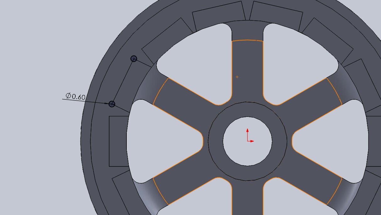
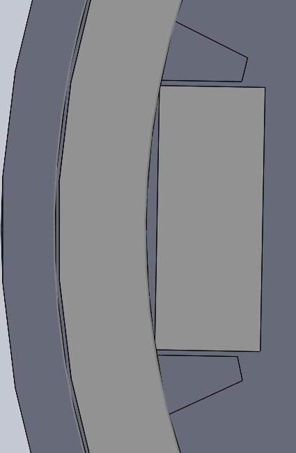
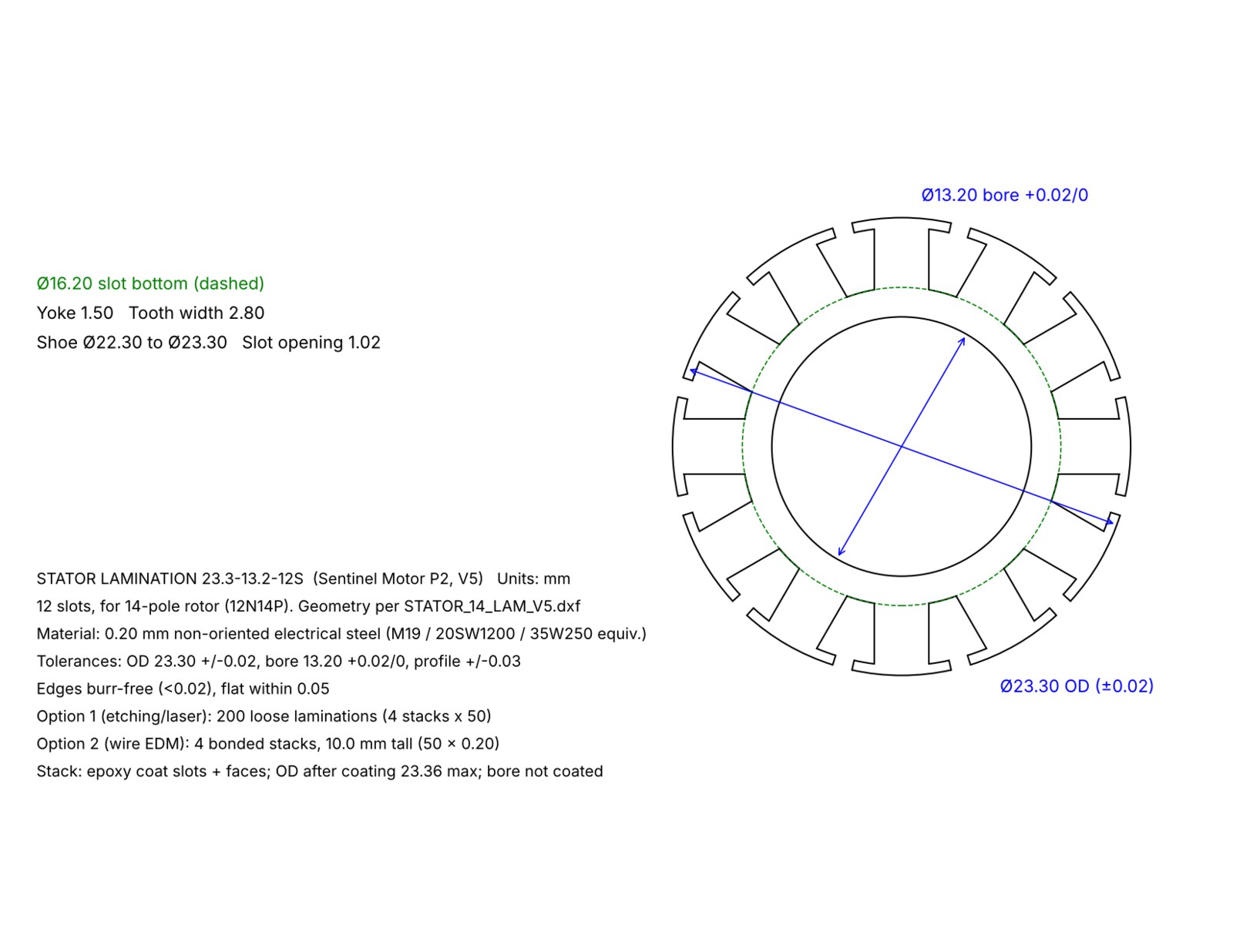
Machining drawings
Sentinel quadcopter
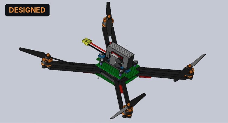
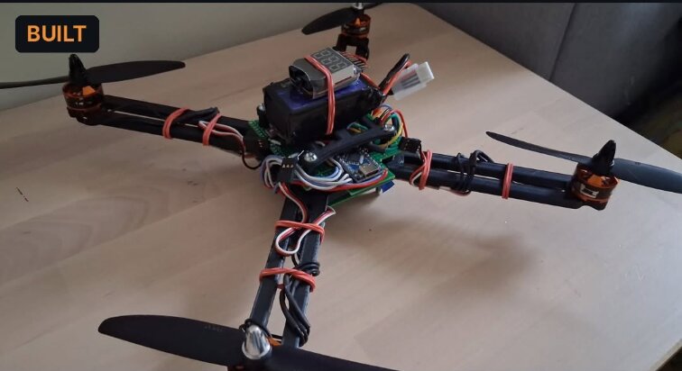
Build a small quadcopter from the subsystem level up, with my own flight-control firmware on an 8-bit microcontroller (32 KB flash).
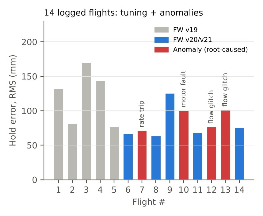
Wrote C/C++ flight control: 200 Hz attitude, altitude and optical-flow position loops. Iterated the frame in CAD (arm V0 → V1_3, legs V1 → V3), split every part to fit a 7 × 7 in print bed, and checked arm stress with FEA. Logged 14 channels of telemetry at 25 Hz on every flight. Designed its custom brushless motor controller (section 03).
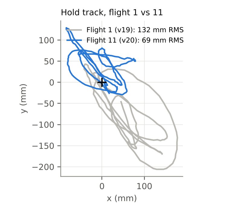
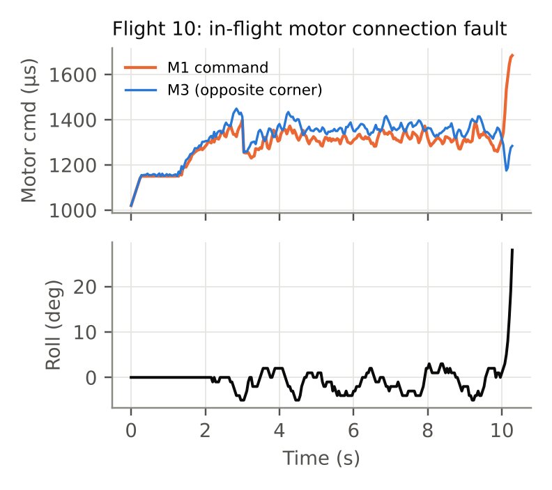
Stable 18 s position holds at 300 mm. Hold error dropped from 132 to 69 mm RMS across firmware versions, and every flight anomaly was root-caused from the logs.
| Item | Result |
|---|---|
| Thrust budget | ~130 g per motor, ~510 g total; thrust-to-weight ≈ 1.7 |
| Arm FEA | Peak ~5.8 MPa at 3 N per arm (≈2.3× max motor thrust) |
| Yaw bias | Traced to one motor producing ~3.6× the reaction torque of the others |
| Sensors | IMU, time-of-flight altimeter (I²C), optical flow (SPI) |
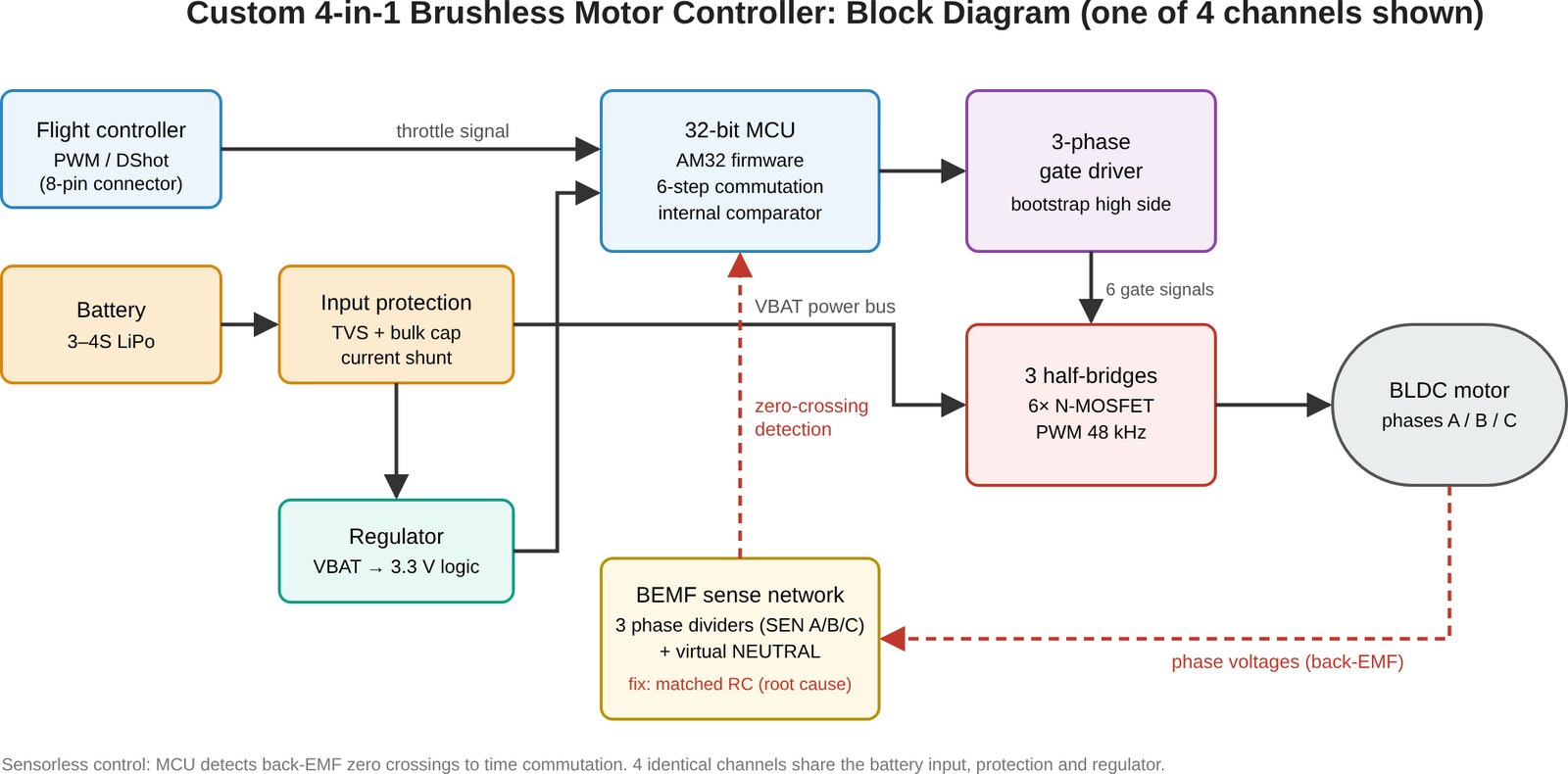
Custom brushless motor controller
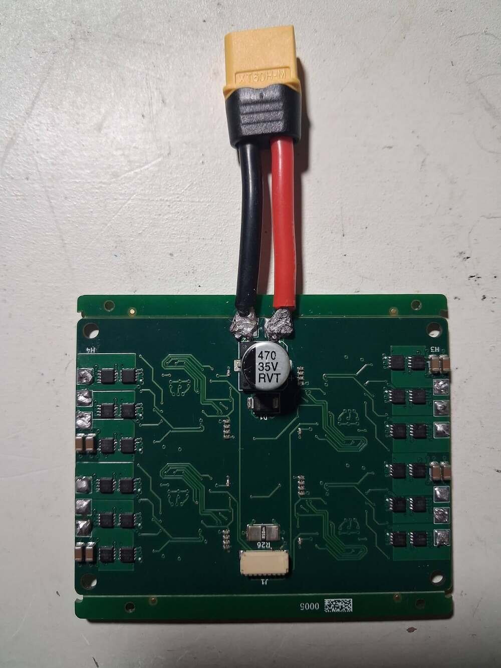
Off-the-shelf motor controllers are a black box. I wanted one I understand down to the comparator, for Sentinel and future aircraft.
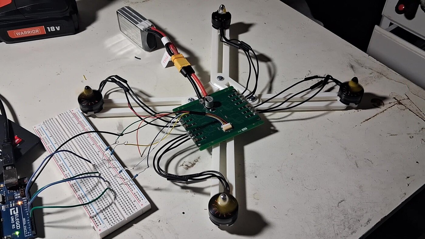
Simulated each block in LTspice, laid out a 4-layer PCB, had it fabricated and assembled, then flashed open-source AM32 firmware to all four channels. When motors lost sync on first spin, I ruled out firmware and power-stage causes in order, then simulated the back-EMF sense network.
Found a filter mismatch putting ~11 µs of false timing error after every PWM edge. Removing one part fixed it, and the board now drives motors on the bench. Next revision matches the sense filters on all channels.
Test equipment
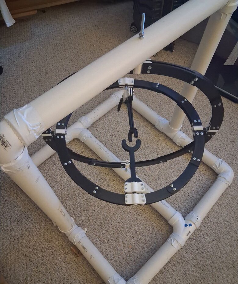
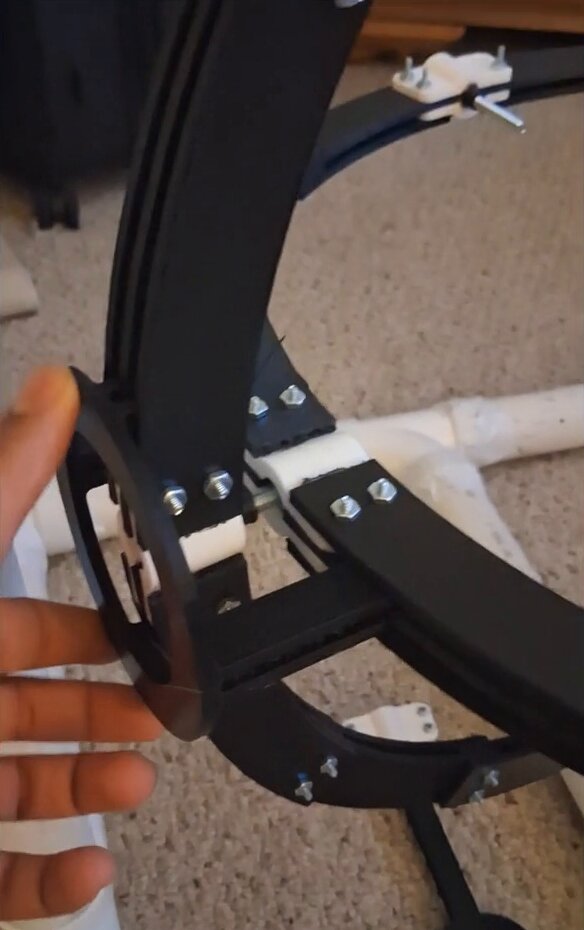
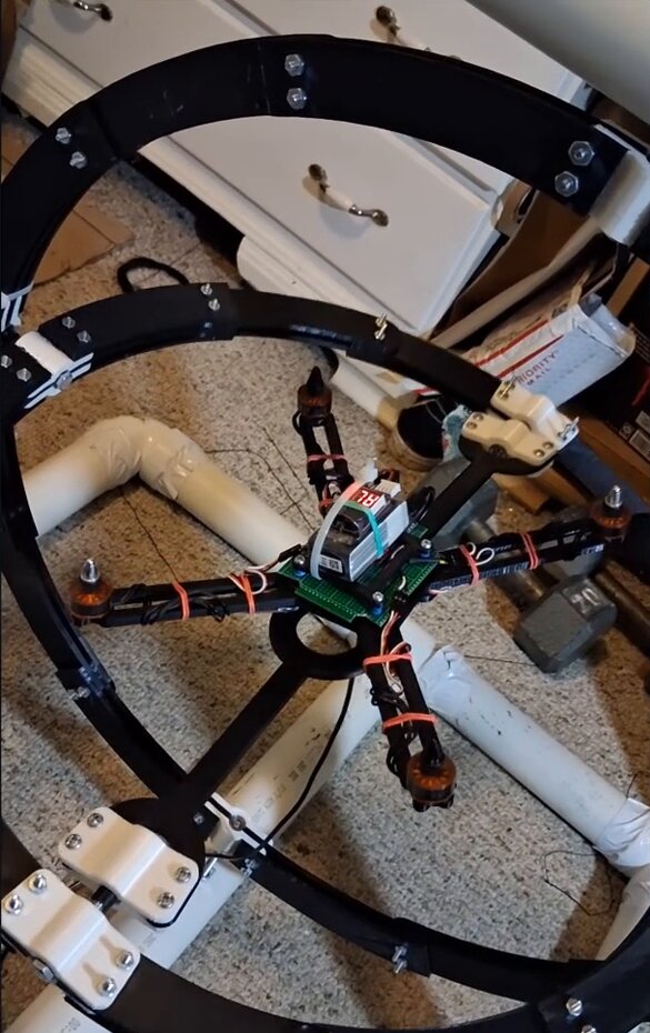
Tune and verify each control loop without risking the aircraft or myself.
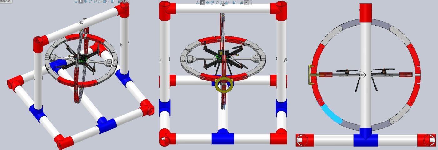
Designed an orbital 3-axis tuning rig with roll, roll-pitch and roll-pitch-yaw configurations (each lockable, so one loop is tuned at a time), plus a linear rig. Built a thrust stand with a load cell (HX711), INA226 voltage/current sensing and an IR RPM sensor, alongside a watt meter.
Measured the thrust budget and motor imbalance that set the flight-controller tuning, and moved first spin-ups off the bench and into a constrained rig.